Adapting Modbus Devices
The
dobot-plusskill supports devices using Modbus RTU and Modbus TCP. This example shows how to use the skill in an AI Agent to adapt end effectors that communicate over Modbus RTU. Three common devices are covered below: OnRobot VG10 (vacuum gripper), DH-Robotics AG-95 (electric gripper), and DH-Robotics PGE-50 (integrated drive-and-control gripper). Instead of writing Lua, HTTP APIs, and UI pages by hand, the Skill generates plugin scaffolding from your device protocol document—you only need to prepareRequirements.mdand invoke/dobot-plusin the IDE.
Example Workflow
Environment Setup
Confirm the following before development. See Development Environment for more detail.
| Dependency | Version / Notes |
|---|---|
| Node.js | v20 or later |
| IDE | Supports Agent Skills (e.g. Cursor) |
| @dobot-plus/cli | Global install; provides the dpt command |
| @dobot-plus/skill | Global install; provides the /dobot-plus skill |
Install:
npm install -g @dobot-plus/cli @dobot-plus/skill@latest
Verify:
node -v    # Should print v20.x or later
dpt -v     # Confirm CLI works
After install, the Skill is deployed to ~/.agents/skills/dobot-plus. Enable Agent Skills in your IDE settings to use it.
Writing Requirements.md (General Requirements)
The Skill does not create or modify Requirements.md. You must write a complete device protocol document in the project root.
Required Content
| Category | Description |
|---|---|
| Communication protocol | Protocol type, baud rate, data bits, parity, stop bits |
| Slave address | Modbus RTU slaveID (list separately per connection method) |
| Register map | Decimal + hex address, name, read/write access |
| Bit fields / value ranges | High/low bytes, bit meaning, enum values, units, and ranges |
| Function semantics | Each atomic operation exposed externally (read / write / control) |
Recommended Outline
- Device overview
- Communication protocol (Modbus RTU parameters and device address)
- Register overview
- Register details (bit fields, enums, units, ranges)
- Operation flow
- Version info and safety notes
Split functions into atomic operations whenever possible—each function should do one thing only.
Generate with AI
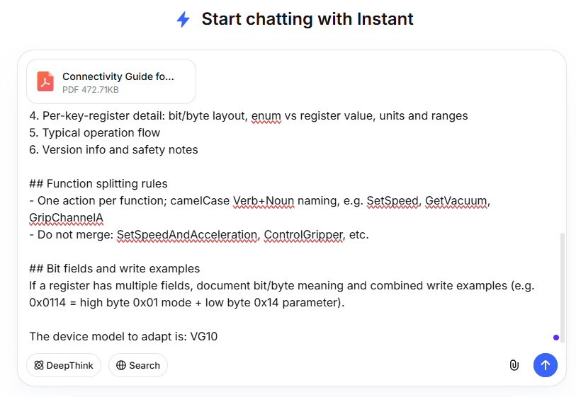
If you have a vendor PDF manual, you can ask a general-purpose AI model to turn the protocol content into Requirements.md, review it, and save it in the project root. Copy the prompt below into ChatGPT, Cursor, or similar tools, and attach the PDF text.
Sample AI prompt (for multi-device manuals, you must specify which model(s) to support):
You are an industrial device protocol documentation assistant. From the manual content I provide, produce a Requirements.md device document that meets the requirements below.

## Output requirements
1. Output Markdown only from my materials; do not invent register addresses, bit fields, or parameters
2. Mark uncertain items as "TBD"; do not guess
3. Keep register names and mode names in English

## Must include
1. Device overview
2. Communication protocol: Modbus RTU parameters (baud rate, data bits, parity, stop bits) and device address (slaveID)
3. Register overview: address (decimal + hex), name, read/write access
4. Per-key-register detail: bit/byte layout, enum vs register value, units and ranges
5. Typical operation flow
6. Version info and safety notes

## Function splitting rules
- One action per function; camelCase Verb+Noun naming, e.g. SetSpeed, GetVacuum, GripChannelA
- Do not merge: SetSpeedAndAcceleration, ControlGripper, etc.

## Bit fields and write examples
If a register has multiple fields, document bit/byte meaning and combined write examples (e.g. 0x0114 = high byte 0x01 mode + low byte 0x14 parameter).

The device model to adapt is: <device model name>
For example, with DeepSeek, drag the device manual into the chat and paste the prompt above:
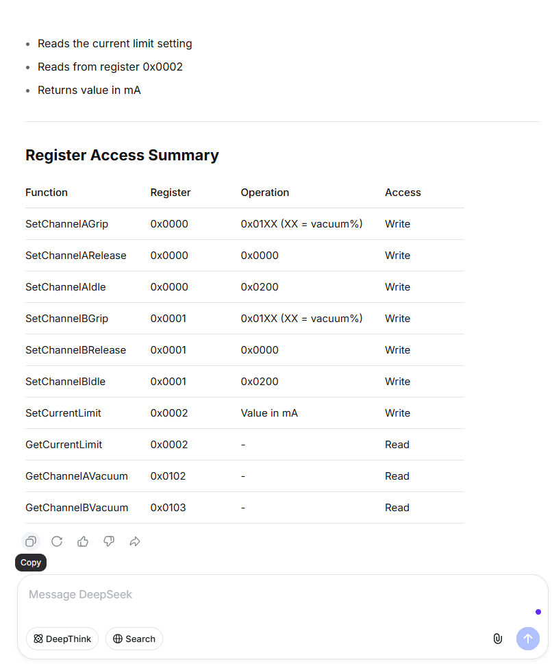
Copy the AI-generated content as your requirements document Requirements.md:
After generation, verify manually:
slaveIDmatches the actual connection method- Register addresses and read/write access match the vendor manual
- Bit-field descriptions are sufficient to derive Modbus write values (e.g. Grip mode + vacuum percentage)
- Functions are split into atomic operations
- Communication parameters match on-site device settings
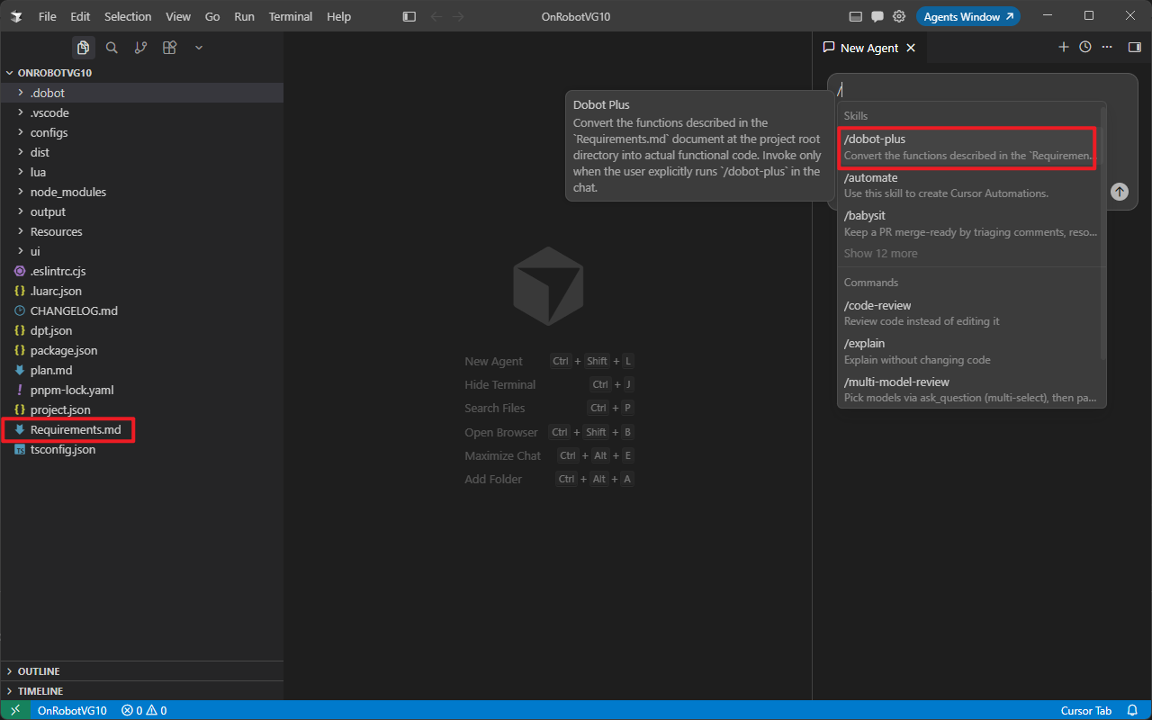
Save the file as Requirements.md in the project root, then invoke /dobot-plus in an IDE Agent session.
Select Agent mode:
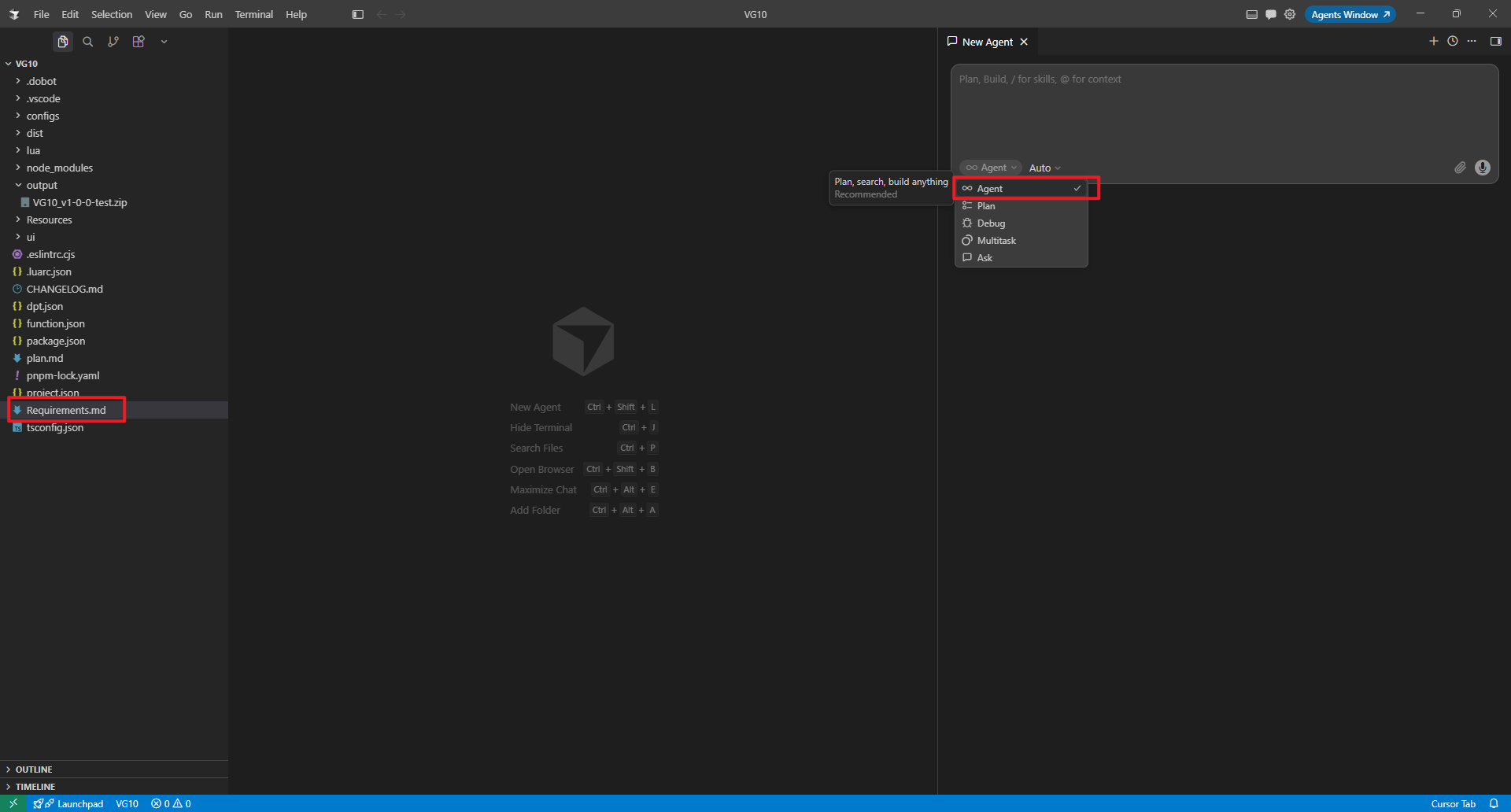
Invoke the /dobot-plus skill:
Device Examples
All three devices communicate over Modbus RTU (RS485). Run dpt create to initialize a plugin project first, then write Requirements.md following the rules above.
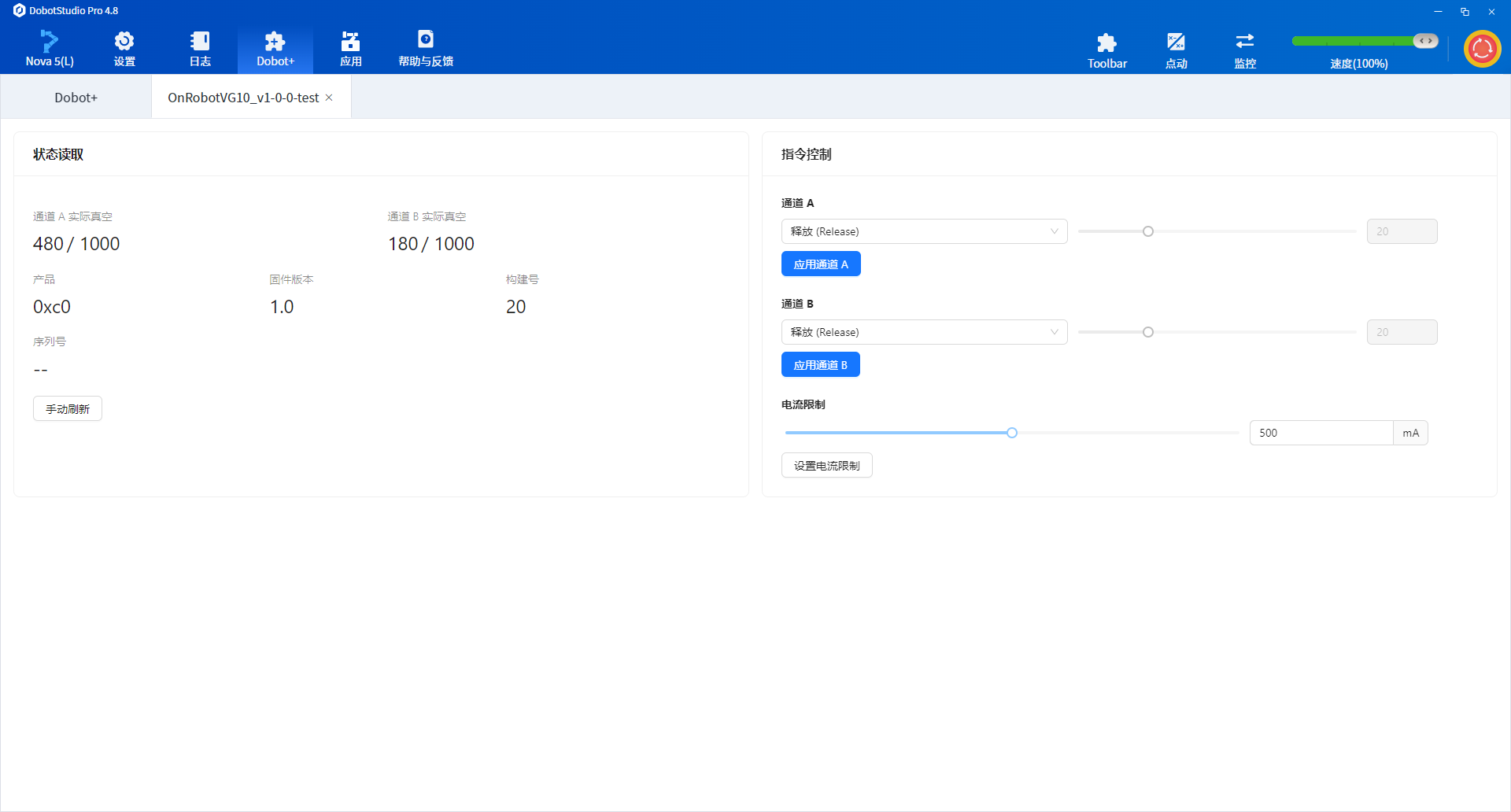
OnRobot VG10
OnRobot vacuum gripper
Create a project:
Initialize an empty Dobot+ plugin with @dobot-plus/cli:
dpt create
Example prompts:
$ dpt create
? Please input plugin name: OnrobotVG10
? Please input plugin description: OnRobot VG10 vacuum gripper plugin
? Please input plugin version: 1-0-0-test
? Please input device IP: 192.168.5.1
Then:
cd OnrobotVG10
Full VG10 Requirements.md example
# VG10 / VGC10 Development Manual

## 1. Device Overview

VG10/VGC10 is OnRobot's vacuum gripper series. This document is based on Connectivity Guide v1.23.0 and describes its underlying Modbus communication interface.

> **Note:** This interface is confidential and intended for experienced integrators only. Improper use may damage the device and void the warranty. OnRobot does not provide further support.

## 2. Communication Protocol

VG10/VGC10 supports **Modbus RTU** over RS485 at the physical layer.

### 2.1 Modbus RTU Settings

| Setting        | Value                   |
| -------------- | ----------------------- |
| Baud rate      | 1000000 bit/s           |
| Start bit      | 1                       |
| Data bits      | 8                       |
| Parity         | Even                    |
| Stop bits      | 1                       |
| CRC checksum   | 16 bit (Modbus default) |
| CRC polynomial | 0xA001 (Modbus default) |

### 2.2 Device Address

| Connection method                    | Device address |
| ------------------------------------ | -------------- |
| Via Quick Changer                    | 65 (0x41)      |
| Via HEX-E/H QC                       | 65 (0x41)      |
| Via Dual Quick Changer (primary 1)   | 66 (0x42)      |
| Via Dual Quick Changer (secondary 2) | 67 (0x43)      |

## 3. Product Identification

Confirm a connected device is VG10/VGC10 via common registers:

| Address      | Register name | VG10/VGC10 value         |
| ------------ | ------------- | ------------------------ |
| 1536 (0x600) | Product code  | VG10: 0x10 / VGC10: 0x11 |

## 4. Supported Modbus Function Codes

| Function code | Name                          | Purpose                                                     |
| ------------- | ----------------------------- | ----------------------------------------------------------- |
| 3 (0x03)      | Read Holding Registers        | Read one or more consecutive registers                      |
| 6 (0x06)      | Write Single Register         | Set the value of a single register                          |
| 16 (0x10)     | Write Multiple Registers      | Set values of multiple consecutive registers                |
| 23 (0x17)     | Read/Write Multiple Registers | Read and write registers in one operation (write then read) |

## 5. Register Map

### 5.1 Register Overview

| Address      | Register name           | Access       |
| ------------ | ----------------------- | ------------ |
| 0 (0x0000)   | Channel A Control       | Read + Write |
| 1 (0x0001)   | Channel B Control       | Read + Write |
| 2 (0x0002)   | Current Limit           | Read + Write |
| 258 (0x0102) | Channel A Actual Vacuum | Read only    |
| 259 (0x0103) | Channel B Actual Vacuum | Read only    |

### 5.2 Common Registers

The following registers apply to all OnRobot devices:

| Address       | Content                                                   |
| ------------- | --------------------------------------------------------- |
| 0x600         | Product code (VG10: 0x10, VGC10: 0x11)                    |
| 0x604         | Firmware version (high 8 bits: major, low 8 bits: minor)  |
| 0x605         | Firmware build number                                     |
| 0x609 - 0x618 | Serial number (32 bytes, 2 ASCII characters per register) |

---

## 6. Register Details

### 6.1 Channel A Control (0x0000) - Read/Write

Controls vacuum operations for channel A.

**Register value composition:**

- Low byte (Bit 0-7): Control mode
- High byte (Bit 8-15): Target vacuum level (used only in Grip mode)

**Control modes:**

| Register value | Name    | Description                                                             |
| -------------- | ------- | ----------------------------------------------------------------------- |
| 0 (0x0000)     | Release | Release the workpiece; stop the pump if the other channel has no demand |
| 1 (0x0001)     | Grip    | Build and maintain vacuum                                               |
| 2 (0x0002)     | Idle    | Idle mode; neither release nor grip; slightly lower power consumption   |

**Target vacuum level examples:**

| Target vacuum | Register value |
| ------------- | -------------- |
| Release       | 0 (0x0000)     |
| 20%           | 276 (0x0114)   |
| 40%           | 296 (0x0128)   |
| 75%           | 331 (0x014B)   |
| Idle          | 512 (0x0200)   |

> **Note:** The target vacuum level must not exceed 80%.

---

### 6.2 Channel B Control (0x0001) - Read/Write

Controls vacuum operations for channel B. Functionality is identical to Channel A Control; refer to the previous section.

---

### 6.3 Current Limit (0x0002) - Read/Write

Sets and reads the current limit.

| Parameter       | Value   |
| --------------- | ------- |
| Unit            | mA      |
| Default         | 500 mA  |
| Maximum allowed | 1000 mA |

> **Warning:** Do not set this value above 1000 mA.

---

### 6.4 Channel A Actual Vacuum (0x0102) - Read Only

Reads the current actual vacuum level for channel A.

| Parameter | Description                                                                  |
| --------- | ---------------------------------------------------------------------------- |
| Unit      | 1/1000 relative vacuum                                                       |
| Note      | Unlike the setpoint (percentage), this uses thousandths for higher precision |

---

### 6.5 Channel B Actual Vacuum (0x0103) - Read Only

Reads the current actual vacuum level for channel B. Specifications are the same as Channel A Actual Vacuum.

---

## 7. Operation Flow

### 7.1 Basic Control Flow

1. **Configure current limit (optional)**
   - Write the current limit value (mA) to register 0x0002

2. **Set and start vacuum gripping**
   - Write a Grip command with target vacuum to register 0x0000 (channel A) or 0x0001 (channel B)
   - Example: `0x0114` = grip at 20% vacuum, where **01 is the mode in the high 8 bits; 14 is the parameter in the low 8 bits**

3. **Monitor actual vacuum**
   - Read register 0x0102 (channel A) or 0x0103 (channel B)
   - Obtain actual vacuum in thousandths

4. **Release workpiece**
   - Write `0x0000` to the corresponding channel control register

5. **Idle state**
   - Write `0x0200` to the corresponding channel control register

### 7.2 Dual-Channel Usage

Both channels of VG10/VGC10 can be controlled independently:

- Channel A is controlled by register 0x0000
- Channel B is controlled by register 0x0001
- When one channel releases, the pump continues running if the other channel still requires vacuum

---

## 8. Version Information

| Item                                  | Value                      |
| ------------------------------------- | -------------------------- |
| Based on document version             | Connectivity Guide v1.23.0 |
| Applicable devices                    | VG10, VGC10                |
| Minimum firmware version (115200 bps) | v2.0.3                     |
| Communication protocol                | Modbus RTU (RS485)         |

---

## 9. Safety Notes

- Do not exceed 80% target vacuum
- Do not exceed 1000 mA current limit
- Use this interface only with sufficient integration experience
- Always read the device operating instructions before use
- Improper use may damage the device and void the warranty
After generation, verify:
slaveIDinRequirements.mdmatches the actual device slave ID- Register mapping matches the developer manual
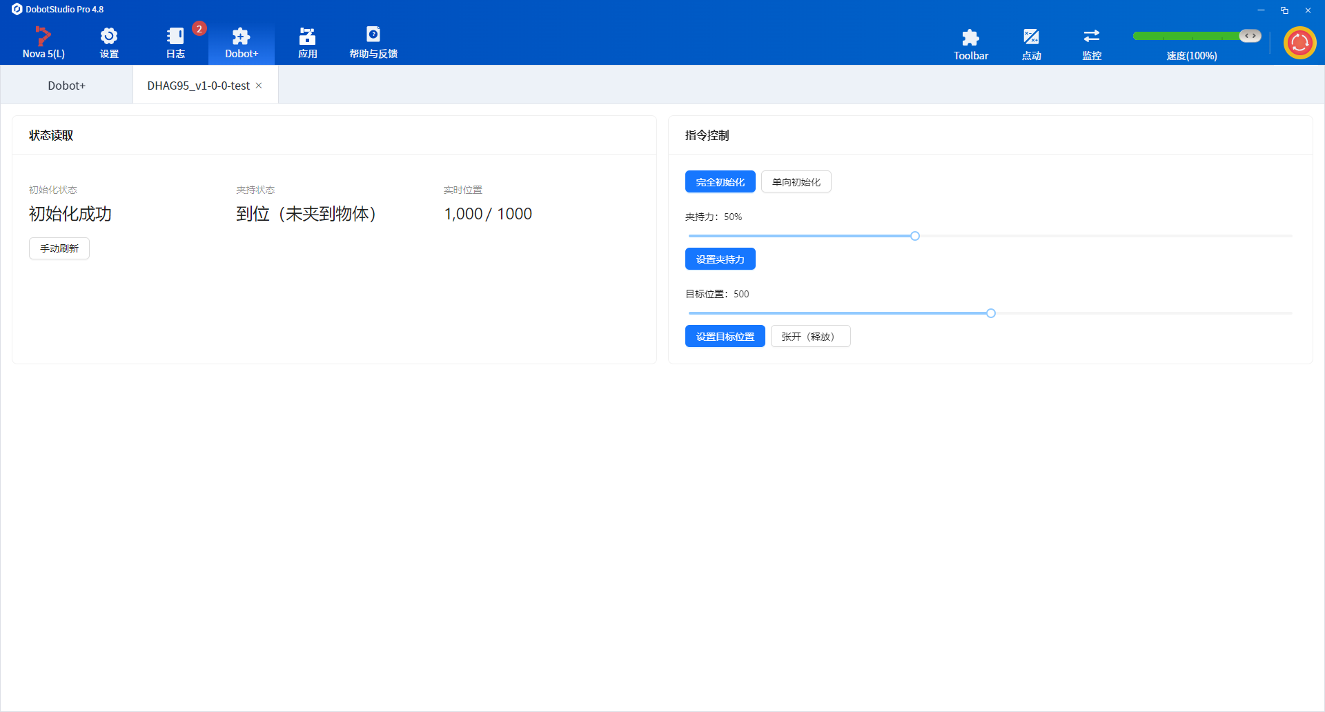
DH AG-95
DH-Robotics electric gripper
Create a project:
dpt create
# Plugin name: DhAG95
# Description: DH-Robotics AG-95 electric gripper plugin
cd DhAG95
Full AG-95 Requirements.md example
# AG Series Electric Gripper — Modbus RTU Reference

## 1. Communication Parameters

| Parameter | Default    |
| --------- | ---------- |
| Modbus ID | 2          |
| Baud rate | 115200     |
| Data bits | 8          |
| Stop bits | 1          |
| Parity    | None       |
| Protocol  | Modbus RTU |

---

## 2. Register Quick Reference

### Control registers (writable)

| Function        | Address | Range       | Description                   |
| --------------- | ------- | ----------- | ----------------------------- |
| Initialize      | 0x0100  | 0x01 / 0xA5 | One-way init / full init      |
| Force           | 0x0101  | 20-100      | Gripping force (%)            |
| Target position | 0x0103  | 0-1000      | Permille; 0=open, 1000=closed |

### Status registers (read-only)

| Function        | Address | Return values | Description                                    |
| --------------- | ------- | ------------- | ---------------------------------------------- |
| Init status     | 0x0200  | 0/1/2         | 0=not initialized, 1=success, 2=in progress    |
| Grip status     | 0x0201  | 0/1/2/3       | 0=moving, 1=in position, 2=gripping, 3=dropped |
| Actual position | 0x0202  | 0-1000        | Current position                               |

---

## 3. Command Examples

> All examples below use Modbus ID 2 (address byte 0x02)

### 1. Initialize gripper

#### Full initialization (close then open to calibrate stroke)

```plaintext
Send:    02 06 01 00 00 A5 48 4D
Response: 02 06 01 00 00 A5 48 4D
```

#### One-way initialization (per init-direction register)

```plaintext
Send:    02 06 01 00 00 01 49 F6
Response: 02 06 01 00 00 01 49 F6
```

> Initialization takes 0.5–3 s; do not control until complete

---

### 2. Set force

```plaintext
# Set force to 50%
Send:    02 06 01 01 00 32 59 FD
Response: 02 06 01 01 00 32 59 FD
```

| Force (%) | Hex data |
| --------- | -------- |
| 20        | 00 14    |
| 50        | 00 32    |
| 100       | 00 64    |

---

### 3. Grip object (set target position)

```plaintext
# Move to position 500 (permille)
Send:    02 06 01 03 01 F4 78 21
Response: 02 06 01 03 01 F4 78 21
```

| Position          | Hex data |
| ----------------- | -------- |
| 0 (open)          | 00 00    |
| 500 (half closed) | 01 F4    |
| 1000 (closed)     | 03 E8    |

---

### 4. Release object (open to position 0)

```plaintext
Send:    02 06 01 03 00 00 79 F6
Response: 02 06 01 03 00 00 79 F6
```

---

### 5. Read grip status

```plaintext
Send:    02 03 02 01 00 01 D4 72
Response: 02 03 02 00 02 23 98
```

| Return | Status                  |
| ------ | ----------------------- |
| 00 00  | Moving                  |
| 00 01  | In position (no object) |
| 00 02  | Object gripped          |
| 00 03  | Object dropped          |

---

### 6. Read actual position

```plaintext
Send:    02 03 02 02 00 01 24 72
Response: 02 03 02 03 E8 B8 FA
```

> 0x03E8 (hex) = 1000 (decimal)

---

### 7. Read initialization status

```plaintext
Send:    02 03 02 00 00 01 85 B2
Response: 02 03 02 00 01 B8 44
```

| Return | Status          |
| ------ | --------------- |
| 00 00  | Not initialized |
| 00 01  | Initialized     |
| 00 02  | Initializing    |

---

## 4. Combined Operation Flows

### Full grip sequence

```plaintext
1. Initialize (if not initialized)
   Send: 02 06 01 00 00 A5 48 4D

2. Set force (e.g. 50%)
   Send: 02 06 01 01 00 32 59 FD

3. Set target position (e.g. 500)
   Send: 02 06 01 03 01 F4 78 21

4. Read status to confirm grip
   Send: 02 03 02 01 00 01 D4 72
   → Return 00 02 means object gripped
```

### Release sequence

```plaintext
1. Set target position to 0
   Send: 02 06 01 03 00 00 79 F6

2. Read status to confirm in position
   Send: 02 03 02 01 00 01 D4 72
   → Return 00 01 means in position (no object)
```

---

## 5. Indicator States

| Status           | Indicator                    |
| ---------------- | ---------------------------- |
| Not initialized  | Red blinking                 |
| Initialized      | Blue solid                   |
| Object gripped   | Green solid                  |
| Object dropped   | Green blinking               |
| Command received | Purple blinking (blue + red) |

---

## 6. Notes

1. **Initialize first** — the gripper ignores control commands otherwise
2. Control is allowed only when initialization is complete (**blue solid**)
3. After changing parameters, write `0x01` to `0x0300` to save to Flash
4. After changing fingertips, run full init with `0xA5`
5. IO mode and Modbus mode are mutually exclusive
6. All commands are **hex**; CRC must be computed correctly

---

## 7. CRC Calculation

- CRC-16
- Polynomial: MODBUS (0x8005)
- Initial value: 0xFFFF
- XOR value: 0x0000
- Input/output reflection: Yes
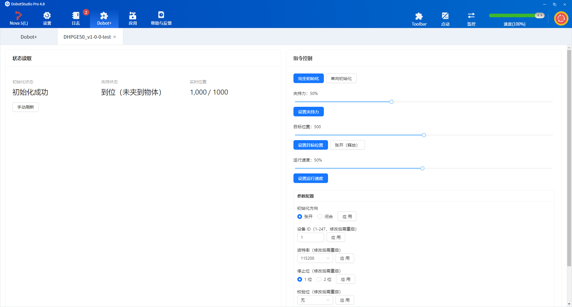
DH PGE-50
DH-Robotics integrated industrial gripper
Create a project:
dpt create
# Plugin name: DhPGE50
# Description: DH-Robotics PGE-50 electric gripper plugin
cd DhPGE50
Full PGE-50 Requirements.md example
# PGE Series Integrated Gripper — Software Development Guide

## Overview

The PGE series is an industrial parallel electric gripper supporting **Modbus RTU (RS485)** and **IO mode**. Control **position, force, and speed** with status feedback.

---

## 1. Communication (RS485 Modbus RTU)

| Parameter | Default |
| --------- | ------- |
| Device ID | 1       |
| Baud rate | 115200  |
| Data bits | 8       |
| Stop bits | 1       |
| Parity    | None    |

> Supported function codes: `03` (read registers), `06` (write single register), `04`, `10`

---

## 2. Register Map

### 2.1 Basic control (read/write)

| Function   | Address (hex) | Description                                | Range                |
| ---------- | ------------- | ------------------------------------------ | -------------------- |
| Initialize | 0x0100        | Write 0x01: homing; 0xA5: full calibration | Write only           |
| Force      | 0x0101        | Gripping force (%)                         | 20–100 (0x14–0x64)   |
| Position   | 0x0103        | Target position (permille)                 | 0–1000 (0x000–0x3E8) |
| Speed      | 0x0104        | Run speed (%)                              | 1–100 (0x01–0x64)    |

### 2.2 Status feedback (read-only)

| Function        | Address (hex) | Return values                                                 |
| --------------- | ------------- | ------------------------------------------------------------- |
| Init status     | 0x0200        | 0: not initialized; 1: success; 2: initializing               |
| Grip status     | 0x0201        | 0: moving; 1: in position, no object; 2: gripping; 3: dropped |
| Actual position | 0x0202        | Current position (permille)                                   |

### 2.3 Configuration (read/write)

| Function           | Address (hex) | Description                                               |
| ------------------ | ------------- | --------------------------------------------------------- |
| Save parameters    | 0x0300        | Write 1 to save to Flash                                  |
| Init direction     | 0x0301        | 0: open; 1: close                                         |
| Device ID          | 0x0302        | 1–247                                                     |
| Baud rate          | 0x0303        | 0: 115200; 1: 57600; 2: 38400; 3: 19200; 4: 9600; 5: 4800 |
| Stop bits          | 0x0304        | 0: 1 bit; 1: 2 bits                                       |
| Parity             | 0x0305        | 0: none; 1: odd; 2: even                                  |
| Auto init on power | 0x0504        | 0: off; 1: on                                             |

---

## 3. Command Examples

### 3.1 Initialize gripper

```text
Send:    01 06 01 00 00 01 49 F6
Response: 01 06 01 00 00 01 49 F6
```

### 3.2 Set force to 30%

```text
Send:    01 06 01 01 00 1E 59 FE
Response: 01 06 01 01 00 1E 59 FE
```

### 3.3 Set position to 500‰ (50% stroke)

```text
Send:    01 06 01 03 01 F4 78 21
Response: 01 06 01 03 01 F4 78 21
```

### 3.4 Set speed to 50%

```text
Send:    01 06 01 04 00 32 48 22
Response: 01 06 01 04 00 32 48 22
```

### 3.5 Read grip status

```text
Send:    01 03 02 01 00 01 D4 72
Response: 01 03 02 00 02 39 85  (02 = object gripped)
```

### 3.6 Save all configuration

```text
Send:    01 06 03 00 00 01 48 4E
Response: 01 06 03 00 00 01 48 4E
```

---

## 4. IO Mode Control

### 4.1 Input pins (NPN, 0V active)

| INPUT1     | INPUT2     | Action          |
| ---------- | ---------- | --------------- |
| High-Z (0) | High-Z (0) | Parameter set 1 |
| 0V (1)     | High-Z (0) | Parameter set 2 |
| High-Z (0) | 0V (1)     | Parameter set 3 |
| 0V (1)     | 0V (1)     | Parameter set 4 |

### 4.2 Output feedback (NPN)

| OUTPUT1 | OUTPUT2 | Status                 |
| ------- | ------- | ---------------------- |
| High-Z  | High-Z  | Moving                 |
| 0V      | High-Z  | In position, no object |
| High-Z  | 0V      | Object gripped         |
| 0V      | 0V      | Object dropped         |

---

## 5. Development Notes

- **Initialize** before control (write 0x01 or 0xA5 to 0x0100)
- After init or parameter changes, **save to Flash (0x0300)** is recommended
- IO and RS485 can coexist; on conflict, **first command wins**
- Do **not** send control commands during initialization (~0.5–3 s)
- Changing ID or baud rate requires a **gripper restart**

---

## 6. Debugging Tips

- Use vendor tools or any serial tool (e.g. Modbus Poll)
- Wiring: 24V, GND, 485A, 485B
- USB-to-RS485 adapter recommended for PC debugging
Using the Agent Skill
Open the plugin project and run this slash command in IDE Chat:
/dobot-plus
Import and Use
- Open DobotStudio Pro → Dobot+ plugin manager
- Uninstall any same-name plugin first
- Import the zip from
output/ - Use the plugin from the nav bar (UI, blocks, scripts)
Package name pattern:
<plugin-name>_v<major>-<minor>-<patch>-<status>.zip
See Quick Start — Build & Use for screenshots and details.
Example Plugin UI Screenshots
- OnRobot VG10
- DH AG-95
- DH PGE-50
FAQ
How to view Modbus communication messages
Create a TCP client using a network debugging tool.
- Use the PC as the TCP client
- Keep the PC connected to the controller's LAN1 Ethernet port
- Connect to IP
192.168.5.1on port60000(use the robot arm's actual IP address; the default IP for the control cabinet's LAN1 port is192.168.5.1) - Set the message format to
HEX. - When debugging with a virtual controller, the IP address used when creating the TCP client must match the virtual controller's actual IP. You can view the virtual controller IP on the DobotStudio Pro home page under IP Address.
Once connected, you can view messages sent by the plugin to the end device and responses returned by the end device.
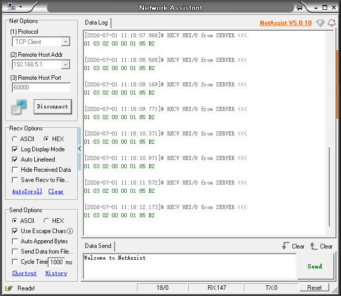
Common TCP debugging tools include:
How to adapt Modbus TCP devices
Check that Requirements.md includes the required Modbus TCP fields:
- IP address
- Port number
Once these values are complete and correct, no other steps are needed—the Agent adapts automatically.
Manual build when Agent packaging fails
When development and debugging are complete, run from the project root:
dpt build
Outputs:
dist/— built plugin sources for inspectionoutput/— zip package named<plugin-name>-<version>.zipfor import
Skill reports missing Requirements.md
Ensure Requirements.md is in the project root with full protocol parameters, register addresses, and function definitions. The Skill will not create it for you.
Modbus communication fails
- Match controller RS485 settings to
Requirements.md - Check RS485 wiring and bus address conflicts
- Verify IP in
dpt.jsonwhen usingdpt devwith a real device
Poor Agent results
- Confirm on-site communication parameters match the manual
- Review
Requirements.mdfor ambiguous or contradictory descriptions - Check the Agent model: use GPT-5.4 or newer in VS Code Copilot; Auto mode in Cursor generally works well